Design an ideal transformer and generate an LTspice model. Enter a turns ratio or impedance ratio to get started.
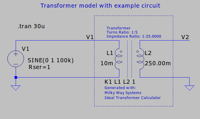
This tool converts between a transformer's turns ratio, impedance ratio, and winding inductance values. It utilizes a two-winding transformer model as shown below. It also generates an LTspice transformer model based on your parameters. The transformer parameters follow the conventions below:

where:
There are several ways to use this tool:
Designing for turns ratio: If you have a target turns ratio in mind, enter its value. The corresponding impedance ratio and secondary inductance will appear. The primary inductance is set to 10mH by default, but may be adjusted as needed. The transformer model is now fully characterized. An LTspice model is generated and may be downloaded using the button at the bottom of the calculator.
Designing an impedance transformer: Similarly, if you have an impedance ratio in mind, enter its value. The corresponding turns ratio will appear, along with the secondary inductance.
Deriving parameters based on winding inductance: Finally, if you know the inductance of the primary and secondary, fill in the primary inductance and secondary inductance fields. The corresponding turns ratio and impedance ratio will appear.
This tool creates a transformer model that you can download and use in LTspice. It is a coupled inductor model, where each winding is represented as an inductor. The inductors are magnetically coupled to each other using a K-statement SPICE directive. The model uses perfectly coupled windings by default. Learn more about transformer models in LTspice here: Using Transformers in LTspice/Switcher CAD III
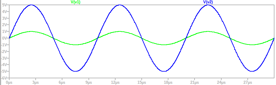
The following model was created by inputting a turns ratio of 1:5 () and winding 1 inductance () of 10mH. The test circuit applies a 1V, 100kHz sine wave to the transformer's input at winding 1. The model was run, and the transformer input and output voltages ( and ) plotted. As expected, the transformer boosts the 1V input to 5V.
We define the transformer's turns ratio () to be the number of turns on winding 2 (), divided by the number of turns on winding 1 ():
In an ideal transformer, the winding voltages ( and ) scale with the turns ratio . Under our our conventions, a transformer with greater than one will boost or step up a voltage applied across winding 1. This relationship is given by:
The winding currents ( and ) scale in the opposite direction. In other words, a transformer with above one will scale down a current applied to winding 1:
Transformers can also scale an impedance up or down. For instance if an impedance is placed at the output of a transformer (), the impedance looking into the transformer () will depend on both and the turns ratio (). can be computed with the formula below, which assumes that the impedance of the magnetizing inductance is large enough to be ignored at the frequency of interest.
The winding inductances ( and ) relate to according to the following formula. This result follows because inductance in proportional to the square of the number of turns on a winding.