Design a voltage divider using standard resistor values. To get started, enter your desired input and output voltages.
This calculator designs voltage dividers using standard resistor values. You enter input voltage and the desired target output voltage, and the calculator provides several voltage divider designs. You can fine tune the results by choosing as desired resistor series and setting a target current
The voltage divider is designed with the following conventions. The input voltage Vin is applied to the upper resistor R1, and the output voltage Vout is taken at the node connecting R1 and R2.

Enter your voltage divider's input voltage Vin in the Input voltage field. Enter your divider's target output voltage Vout in the Output voltage field. The results will appear below in a table. Each row shows a solution consisting of a set of resistor values. The results are sorted from best to worst by output voltage error. The voltage divider's current is shown in the last column.
By default, the calculator searches for solutions with a current near 1mA, using E24 (5% tolerance) resistors. The resistor series and target current can be adjusted as described below.
While we're primarily concerned with output voltage, current is also an important consideration. If too high, the divider will dissipate more power than necessary. If too low, the divider's output resistance will be high, making it more sensitive to drooping under load.
By default, the calculator is set to 1mA with a tolerance of +/-30%. You can leave it as is, or adjust the current and tolerance to suit your needs. Setting a tighter tolerance on current will reduce the number of available solutions, which might cause less optimal voltage results. You can experiment with loosening and tightening the current tolerance as needed.
To set the nominal current, enter the desired value in the Nominal current field and select a desired tolerance from the Current tolerance menu.
the calculator will find solutions from a set of standard component values. By default, the resistor series is set to E96, which is typically used for 1% tolerance resistors. You can change the series if desired using the Resistor Series menu.
Let's assume that you need to generate a 1.0V output from a 5.0V bus. Power consumption isn't too critical in your design. Also, the output impedance isn't too critical since the voltage divider will be driving a very high impedance input. However, you would like the 1.0V output to be quite accurate, with an error of less than 0.5%
To start, enter the 5V input voltage into the Input voltage field and 1V into the Output voltage field. We'll leave the default Nominal current of 1mA as is. We'll also leave the Current tolerance set to its default value for now. To meet the accuracy requirement, we'll need to use precision resistors. The Resistor series input can be left at its default of E96, since it is the largest series that precision resistors are available in.
We're all set with the inputs. The results will appear in a table:
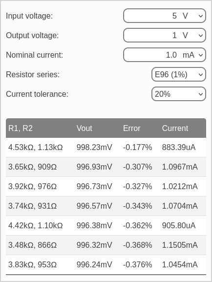
The best result is shown in the first row, with upper and lower resistor values (R1 and R2) set to 4.53kΩ and 1.13kΩ. The resulting output voltage is 998.2mV, with an error of -0.177% compared to the target voltage of 1.0V.
That's pretty good, but we may be able to do better by relaxing the current tolerance. We can try adjusting the Current tolerance input to a higher value re-running the calculator. Raising the tolerance to 70% yields an exact result for output voltage:

The top result, using R1 and R2 values of 10.2kΩ and 2.55kΩ, provides an exact 1.0V output. However, note that the current is now 392.2uA, which is somewhat lower than the Nominal current input.